 The resistor pride flag (I believe originally created by @byjp@hachyderm.io on mastodon, though image search isn’t linking to the actual post) would be a perfect design for an embroidered patch… and there’s an embroidery machine at the library… the only issue being finding gold and silver thread for it…
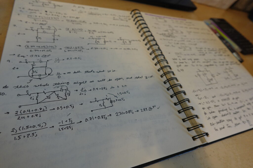
Magnetic circuits, ancient Greek, Britten’s The Turn of the Screw.


Ah yes… I remember now why I gave up on compiling the assembly files from class on Linux. It wasn’t because it was too hard (though, yeah, CCS doesn’t do assembly, so you need to go the makefile/manual compilation/linking/etc route.) It was because the files I want to test are in Keil ARM assembly, and the GCC toolchain needs GNU ARM assembly. Which is very similar! Just a few syntax changes! If only there were some tool, maybe the most hyped piece of software of the modern era, that was supposed to be good at… switching words around?
So I paste a file into chatgpt and asked it to translate this keil arm assembly file into gnu arm assembly. Sure, it says, and begins spitting out… the exact same file. I’m staring at a reference document for gnu assembly. “You’re just giving me the exact same file back,” I tell it. “Apologies for the oversight!” it says, as if not doing anything and pretending you did is just some minor technical error. It tries again, and does seem to be producing something maybe correct, after the first few lines which for some reason it decides to leave unchanged. It stops a quarter of the way through with a button that says “continue?” which I press. (Did I fucking stutter?) It does another quarter, then stops. “That’s not the end,” I inform it. It does another few lines, then stops. I give up and go do something more useful with my time.
If it can’t do this– the kind of simple, rote task that computers are supposed to be good at–

Although I have a Windows partition installed on my laptop, using it means rebooting the computer and, inevitably, running into some rage-inducing reminder of why I do not use Windows.
For my microcontroller class this semester, we were given instructions on creating and flashing programs to the Texas Instruments MSP432E4 micro using the Windows-only Keil IDE. Since I didn’t want to be left behind in the class demonstrations, I didn’t get too far in investigating Linux alternatives besides the vague impression that I might need to write my own makefiles in order to use example code with the GNU ARM toolchain. Wrong!!! As it turns out, Texas Instruments provides a free IDE for its boards that is available for Mac, Windows and Linux… and now that the class is over, I’ve finally figured out I could have been using it all along.
So, here’s a walkthrough of setting up to program the MSP432E4 on Linux. (I’m on Mint, though I doubt there’s much here that’s terribly distro-dependent.)
First, install the Software Development Kit. This isn’t the IDE, it’s a collection of files that the IDE (or you, if you’re a makefile wizard) will use. As of May 2024, the link to get the SDK for the MSP432E4 is here.
When the SDK installer finishes downloading, you will probably need to allow it permission to execute. Right click on it and choose properties > permissions > allow executing file as program, then run it. The setup wizard will ask where you want to install it; probably just keep the default location, which is a folder called “ti” in the home folder of your local user.
Next, download CCS from here. I chose the offline install for Linux. It comes in a compressed folder, so extract it. Inside that folder is a file which begs you to read it first, which will tell you to run the executable.
That installation wizard will check the dependencies on your system. I had a missing dependency, libpython2.7.so.1.0, which was fixed by running
sudo apt-get install libpython2.7
sudo apt-get install libatlas3-base
if your distro doesn’t use the Debian apt utility, or you have different stuff missing, you’ll need to look up how to correct it before continuing.
After all the dependencies are OK, it will suggest installing itself inside of the ti folder that the SDK already made, so do that. Choose “Custom installtion” and select “SimpleLink MSP432 low power + performance MCU”. Keep the default debug probe selected, I guess, idk what the others are.
When the installer is finished, it tells you to run the driver install script before anything else, so go to the file path it provides and run sudo ./install_drivers.sh. Mine worked fine without rebooting but it will warn you some distros need you to reboot for it to take effect.
You can now launch the IDE from the icon in the ti/ccs12.x.x folder! The first time you launch it, it will ask you what you want to use as a workspace directory. I already have a folder I’m planning on keeping all my microcontroller stuff in, so I chose that one and selected “Use as default and do not ask again.”
Time to try it out with some example code from 2DX3! I downloaded a fresh copy of the provided Studio 4A example code from Avenue. Because it was created using the Keil IDE, it has some extra files and directories generated by Keil that aren’t needed.

From the Getting Started window of CCS, choose New Project. In the wizard that opens, make sure you set the correct board, and since we already have a project with a main function, choose to create an empty project with no main.c file.

The new project should now be visible in the Project Explorer window at the left side of the screen. Right-click on the project name and choose “add files”. Add all of the .c and .h files to the project, and then confirm that you would like to copy them instead of just linking to them.

Press the hammer icon to build the project, and the arrow going into a folder to flash it to the board.

That’s it! Since this code is flashing an external LED from PN2, I attached the circuit to test it:
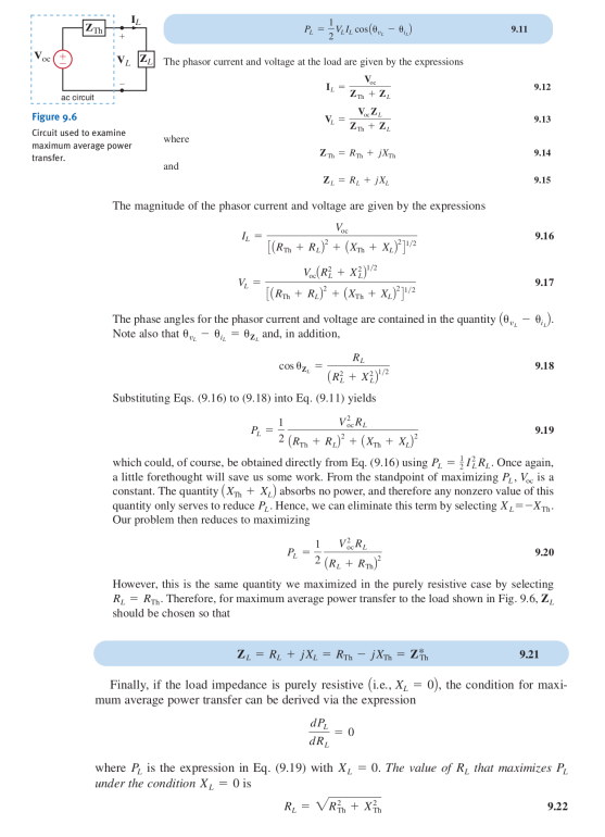
This semester I took an introductory class on electrical circuit analysis. One of the concepts introduced was impedance matching: the idea that if you want to deliver maximum power to a load, the amount that the load “pushes back” on the power source should be equal to (the complex conjugate of) the amount the rest of the circuit pushes back. If you were writing a textbook, you would convince your readers like so:
But what if you weren’t writing a textbook, and wanted to convince someone who was planning on simply getting up and walking away the moment any of those libertine little d’s or, god forbid, the imaginary unit (or the jmagjnary unjt, as the case may be) made an appearance?
Then you could say, imagine you are playing that game where you put a jump rope on the ground and send a pulse through it. You want to try to make sure that the pulse that reaches some given point on the jump rope is, as precisely as possible, exactly the same as the pulse that leaves your hand. You have two choices.
First, you could use two jump ropes tied together, where the two ropes have different thicknesses, or might be made of different materials, or maybe one of them is that beaded kind that hurts like a #!%$ when you hit yourself in the ankle with it:

Or your second option, you could just use one really long jump rope, that has the same thickness and material used throughout.
It’s intuitively obvious that, if there’s a possibility of you being asked to transmit that as-faithful-as-possible pulse to the far side of the rope, you’re way better off with the one long rope. If that isn’t obvious, it’s obvious that you can go buy some jump ropes and try it out for yourself. Of course, the rope that has the same “impedance” throughout is going to transmit the pulse more faithfully, while the tied-together bit is going to muck things up.
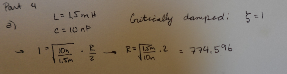
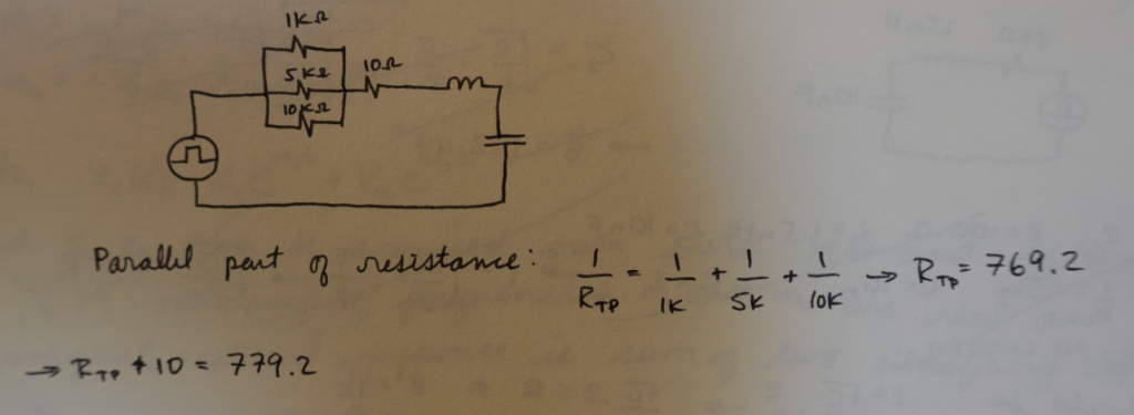
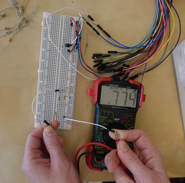
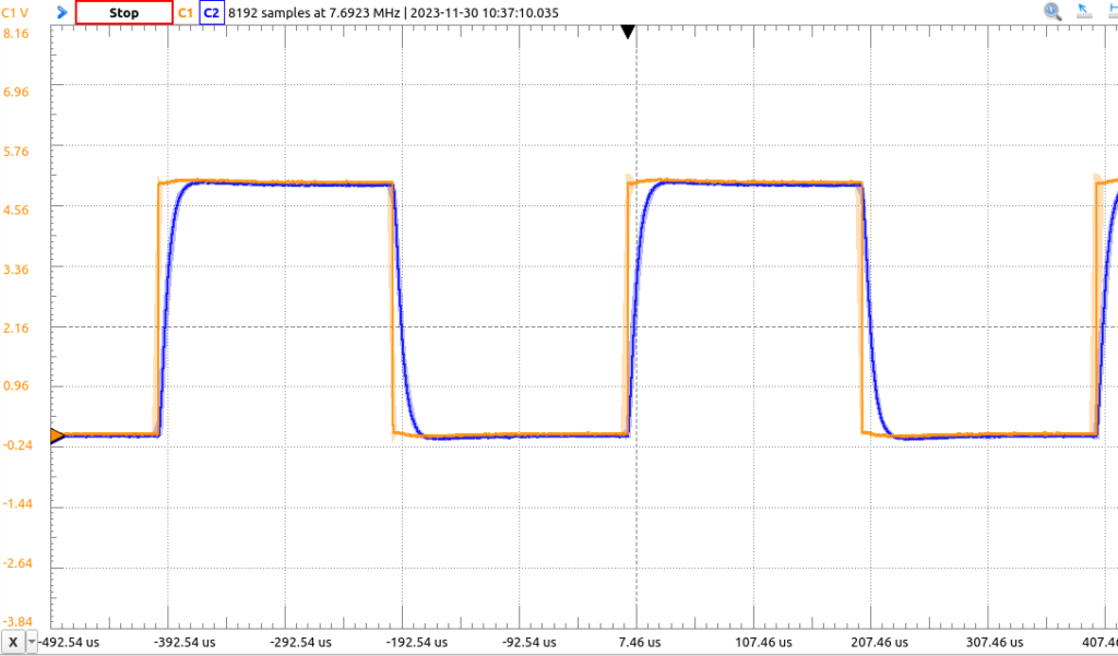
A piece of physical intuition that was less obvious to me at first was that for critical damping. In one assignment, we simulated in software and built in meatspace three different versions of an LRC circuit: an underdamped one, overdamped one, and then figuring out what resistive value to swap in to get it critically damped.
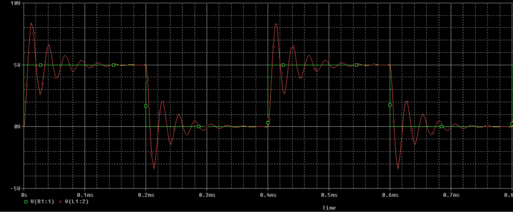
Of course, an underdamped circuit oscillates, as seen in both the simulation and the oscilloscope hooked up to a breadboard:
And an overdamped circuit decays exponentially:

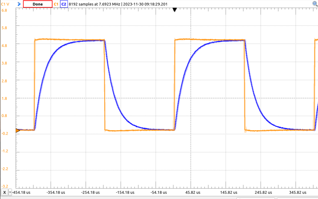
A critically damped circuit– i.e., one where the characteristic equation of the circuit has repeated roots, and there is only one natural frequency– decays faster than an overdamped one:

Why, though? When the words are spoken, it sounds like the thing called “overdamped” should do the thing called “decaying” the fastest. The math, of course, is entirely clear: with repeated roots to the characteristic equation, the solution to the differential equation has an exponential decay term multiplied by the independent variable of time, while the overdamped case has no such thing. So of course the critically damped case has to decay faster. But that’s just a property of multiplication, not a good explanation (and we lost the no-libertine-d’s-or-i’s-or-j’s observer some time ago.)
The physical intuition, then: imagine you are dropping a little ball into a glass of some kind of fluid. Your goal is for the ball to come to rest on the bottom of the glass– equilibrium– as quickly as possible. If the fluid is not sticky enough to slow down the ball before it hits the bottom, it will bounce (underdamped.) If the fluid is sticky, it will slow down the ball enough that it won’t bounce– but there is a point of stickiness beyond which any extra stickiness isn’t actually helping to prevent bounces, it’s just delaying the ball reaching the bottom. Just the right stickiness to prevent bouncing, without slowing down the ball’s progress more than necessary, is critical damping; excessive stickiness is overdamping.
Learning phasor analysis; contemplating that it’s almost too metaphorically on-the-nose that analysis of purely real functions can become vastly easier when they are given an imaginary component. A similar feeling to that evoked by the process for solving the Gaussian integral, in which turning a one-dimensional problem into a two-dimensional problem provides an almost offensively simple answer to a seemingly intractable problem.
Project 4 introduced the premise of having “clients” for whom we were tasked with making a product– more or less any product. This seemed to cause wide-scale confusion, since it was not immediately clear what kind of expectation of completeness came along with the introduction of real live human beings who were giving their time and energy to describe their daily lives and health issues to the first-year engineering class. In Project 3, we knew what “success” looked like: if the mechanism dumped the recycling into the bin, we’ve succeeded. The definition of “success” here was somewhat obscure. Was the bare minimum accomplishment supposed to be creating an object ready to be physically given to the clients at the end of the two-month period of the project, with the expectation that they would be able to use it regularly and find it helpful? How useful is the object supposed to be to “count,” especially when compared against the assumed null hypothesis of having one fewer gadgets to keep track of?
Also: what, exactly, would a useful object do? “Problem framing” was supposed to be the focus of the first few weeks of this project, during which the clients, Tim and Kim, came on Zoom to the class lectures; but they didn’t (perhaps had been instructed not to?) actually make any “asks.” Labs for the first few weeks of this process involved mostly group discussions. Unfortunately, the techniques of planning and decision-making that the class was intended to teach, which were required for lab submissions, seemed to actively hinder the process when the goal was so nebulous to begin with. Much has been made during this course of the importance of a “problem statement” that is “solution neutral”; i.e., you want to express the reason for solving a particular problem and the metrics that will tell you whether or not you’ve done so, without committing to, making reference to, or ruling out specific design elements. This makes excellent sense for most professional situations, where a client will come to an engineering firm with a specific thing they need done, made, or improved upon. Solution-neutral problem framing means keeping the big picture in mind and ensuring that the client’s needs aren’t overshadowed by the design process itself.
In this case, however, there seemed to be a lot of confusion about how to generate a “solution-neutral” problem statement without a particularly well-defined problem. Kim and Tim are a couple who both have complex health issues and disabilities. Tim is almost completely blind, and Kim is a power-chair user; there is a large set of problems associated with disability that are simply not solvable, especially not within two months with limited resources of fabrication and, frankly, skill. Many groups seemed to be struggling with the insistence that we state a problem that we were going to solve, without hinting that we had any ideas at all about how to solve it. True solution-neutral problem framing, in this case, would mean committing to solving a problem that you may quickly realize isn’t going to be successfully solved. And there is, of course, an inverse relationship between the significance of a problem and the ease with which it can be solved; the problems of lack of sight, lack of mobility and pain are both the most significant and the ones not likely to be solved in the scope of this project. What’s left, then, is mostly “gadgets” which may or may not end up solving small annoyances.
My group had, then, several different concepts for gadgets to choose between, many of which seemed common to many different groups. Tim talked about the challenges of cooking now that he has entirely lost his sight, and kitchen gadgets are a category where it seemed possible to come up with a well-defined problem to solve within the time available, so a quick glance around the 1P13 classroom revealed a veritable warehouse of souped-up utensils. Our three main contenders were an Arduino-controlled device which read out the level of water being poured into a vessel (a device that already exists in a smaller form factor than we would be able to build, and ended up being created by at least one other group for the project), a cutting board with a bunch of Handy™ attachments, which is what we and several other groups ended up doing, and an auto-cutting fork, which I was a little fond of on the grounds that it was at least unique, if somewhat impractical:
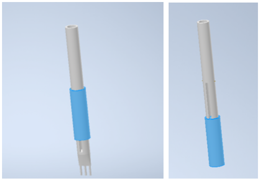 …yeah, it may not look like much, but… OK, there’s no but to that sentence. If we had the ability to fabricate metal, it could have worked– the idea, not exactly clear from a very quick CAD example, would be to have a fork that used a little spring to move a circular wraparound knife up and down; so you can stick the fork into the food, push the knife down to cut a piece of food around the tines, retract the knife (have it held up there or covered somehow so it’s not pointing at your face?), then use it as a fork. As it is, fork tines aren’t a good candidate for 3D printing because they need to get very thin, laser cutting can only cut flat parts along a single plane, and we would have no way of fabricating a circular knife. So, cutting board it was. A groupmate made a cardboard version of the concept, which a) holds the tip of the knife in place, b) has a slide to push food off the board, and c) has a container on the side for the food to be pushed into.
 After this, we spent quite a while trying to figure out how to fabricate a better version with the resources available. The two methods of fabrication available through the class are 3D printing and laser cutting of acrylic. Most of the components we needed were long and flat; theoretically candidates for laser cutting, except that they were longer than the sheet of acrylic that each group was supposedly limited to. (Later we learned that the stated limits were more guidelines than actual rules, but that wasn’t officially circulated information.) Of course there are ways to buy all sorts of these materials, such as a knife– but aren’t we supposed to be, you know, making a thing ourselves? What level of “fabrication” was even expected of us? There was supposed to be a $100 limit on materials, but of course rumours swirled– “I heard that group spent $300 on electronic components and clamed they’d had it all lying around the house,” etc– and direct questions about the expected balance between a professional-looking product and a product we actually fabricated ourselves were met with apparent alarm and confusion.
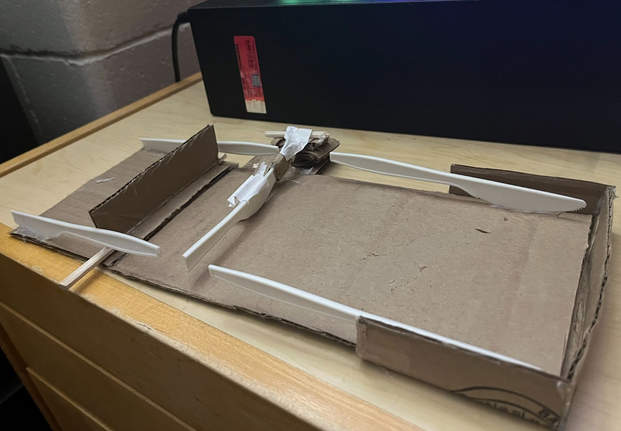
This theoretical speculation was cut short when, one class, a TA informed us that, despite the worksheet’s asking for a “screenshot” of your current prototype, we were actually required to have a new physical prototype built by the next day. So we stopped arguing about how to cut down the 3D printing time on the elaborate knife holder we’d planned. Instead I stopped by Dollarama on my way home from school, bought out their actually pretty extensive craft section, and made this:

 If it’s not clear– there are straight razor blades sticking out of that cleaver-looking thing. My groupmates found this very funny when I brought it to class the next session.
I had assumed that this was just a thing I was building so we’d have something to take a picture of for the submission due the next day; but once it was there, the constraints on fabrication remained, and it wasn’t obvious that we would really be improving it much by replacing wood parts with other materials. Wood is, after all, a perfectly acceptable material for a cutting board as well as many other useful objects, even if “pre-fabricated wood in sizes determined by Dollarama and glued together” isn’t exactly the ideal for high-quality woodworking projects. (I learned during this project that there are woodworking tools available at the Hatch centre; too late to be much use here, since it takes time to get certified to use them, but now that I know that I have all sorts of projects I want to bring there…)
More confusion along the lines of is this, fundamentally, what we are supposed to be doing here? A TA told us the thing basically looked fine as an object to have produced for this project. So my craft project ended up being the final product, with a few modifications– well, actually I had to make the whole thing over just to rearrange the parts a little, because the carpenter’s glue I’d used turned out to work too well. But the final prototype was still Dollarama wood, with a “real” knife instead of my razor-cleaver, and a wooden plate attached to the bottom of the dowel attaching the knife-swivel to the board, so it wouldn’t fall out. There was also a magnetized container added to the side. So, our final product was my first and last cooking vlog.
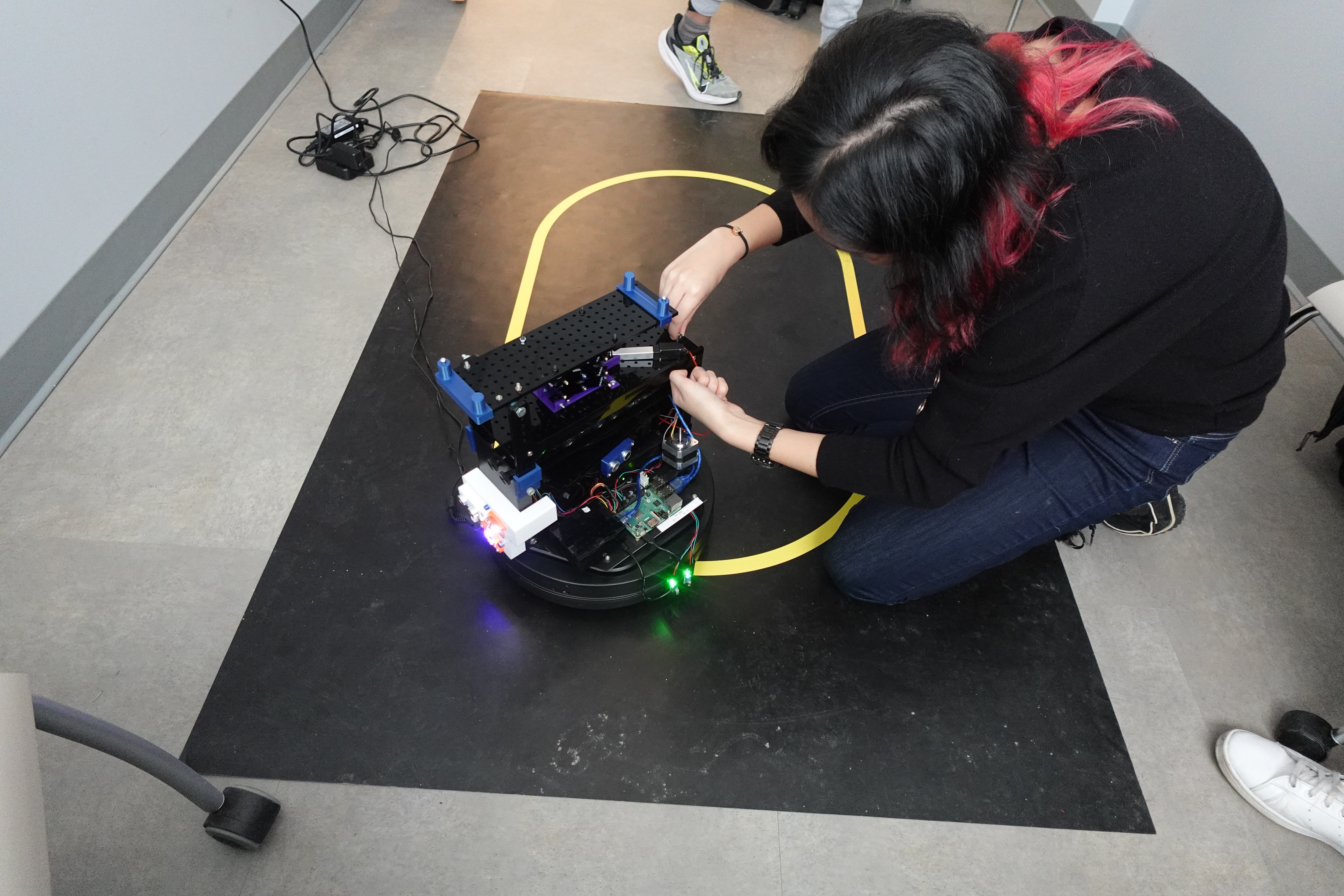
Project 3 was, in my opinion, the most interesting and useful of the four projects of the 1P13 course, as it consisted of a well-defined problem with clear metrics for evaluating how successful your design was. As in the previous project, the groups of students were divided into “Modelling” and “Computation” sub-teams, which had largely seperate goals, though the overall storyline justifying the assignment had to do with the two sub-teams combining their designs into a single system for sorting recycling.
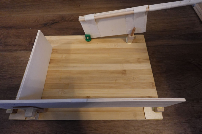
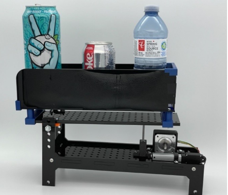
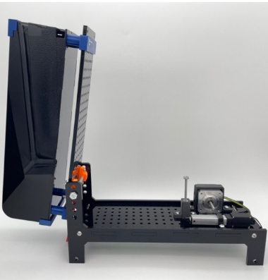
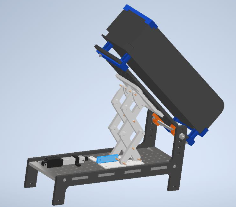
Having done the computing sub-team for project 2, I was on the modelling sub-team for this project. The goal of the physical construction for this project was to design a mechanism that would use either a rotary or linear actuator to raise and lower the container on the upper part of a pre-fabricated hopper, so as to dump out recycled containers contained therein, as in these photos of the starting point provided in the assignment document:
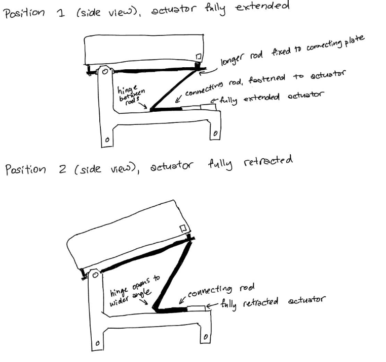
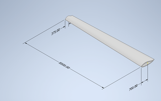
Initially, each member of the group was tasked with coming up with different concepts of how this could be accomplished. My concept for how the linear actuator could be used was pretty much the simplest possible design… a stick. It’s a stick. It raises the top when the linear actuator retracts. Needless to say, I wasn’t exactly jazzed up about the challenges of making this one:

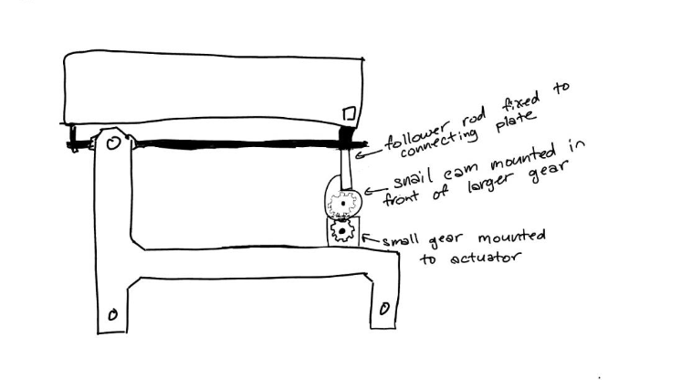
My design for how the rotary actuator could be used was, in my own humble opinion, cooler: it used a set of gears and a cam-and-follower setup to raise and lower the upper platform cyclically as the actuator rotated.
Unfortunately, once we compared this design to the actual size of the hopper our mechanism would need to fit onto, it was clear that the length of cam required to raise the upper platform to a sufficient angle to dump the recycling would not actually fit in the space we had available for the mechanism. actually, all three of us on the modelling team had generated one idea that was cool but impractical, and one that was less visually exciting but more likely to work, all of which were variations on the “it’s a stick, it makes the linear actuator push up” concept.
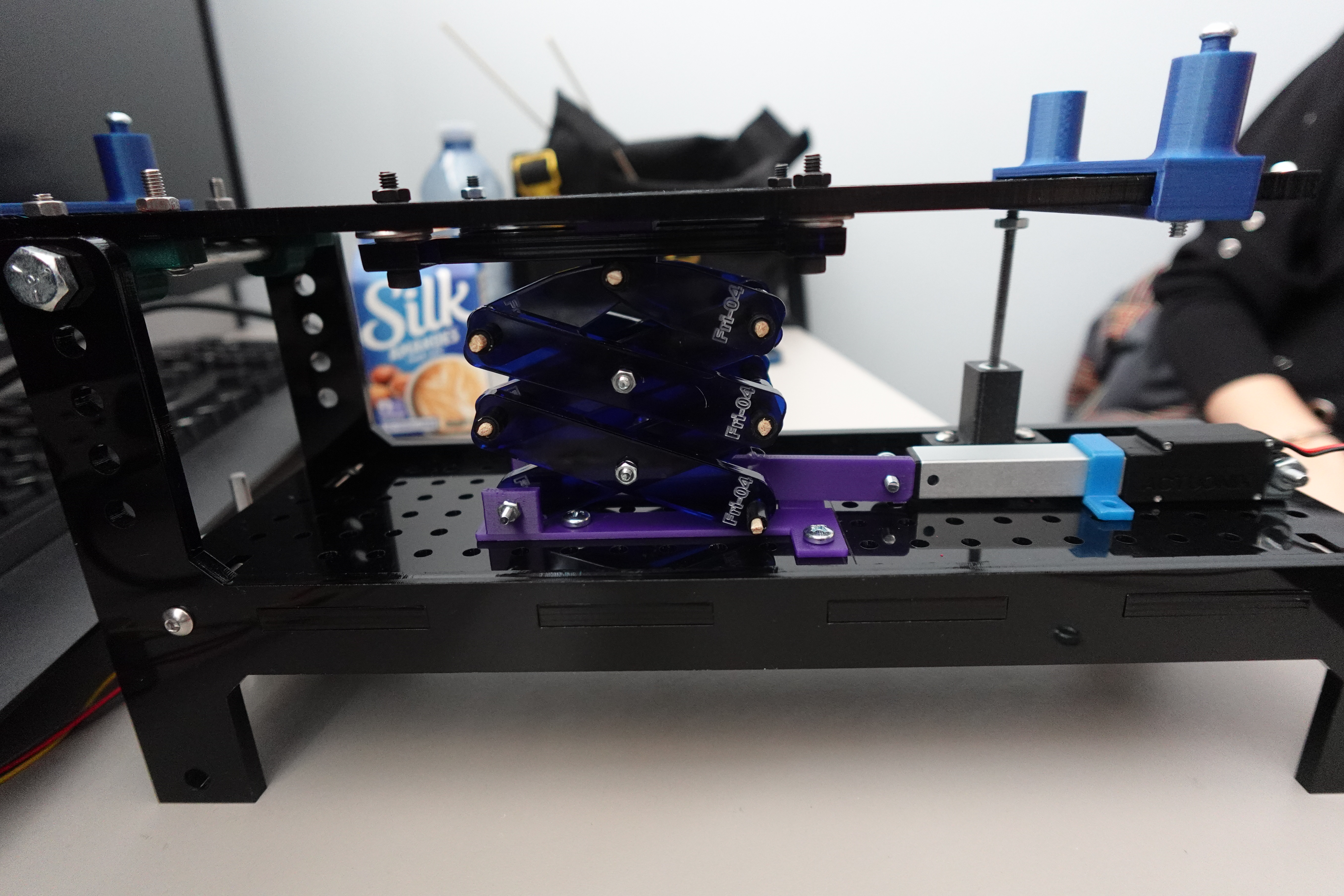
In the end, we settled on the most highly-developed version of the “it’s a stick” concept on the market, a scissor lift.
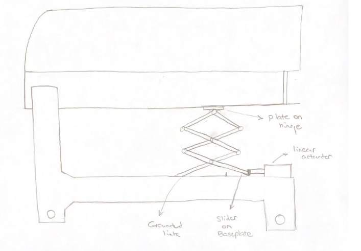
Next we needed to CAD it. Unless the thing is large enough that it makes sense to have different people working on different parts of it, which this wasn’t, it’s a little bit impractical to have multiple people “make” a CAD model of the same object at the same time; instead, the two of us who wanted to work on the CAD model both made our own versions, and we’d use whichever one ended up working better; and the member who preferred to work on fabrication, and had access to a private 3D printer, worked on that side. Unfortunately, the two of us who wanted to make a CAD model were both so enthusiastic about jumping into it that we failed to notice there were downloadable CAD files representing the already-fabricated parts of the hopper that you could use to make sure your mechanism would actually fit, and we showed up at the next class with two separate models of the mechanism, neither of which actually fit the parts provided. Oops! We fixed that for the next class and both attached our models to the given files. In an unexpected sudden death round of “who’s CAD model works better,” something went oddly and catastrophically wrong with the contraints on my classmate’s model, which had been working just fine, right before we were about to show it to a TA, so mine it was, kicking off a long iteration of files on my computer named things like “preminary CAD”, “final CAD”, “really final CAD”, “Actually final CAD after trying it IRL”, etc, as well as a large array of stray files featuring parts in amusingly unphyiscal situations:

(The one aspect of Project 4 that was unambiguously better than Project 3, for me personally: simply giving files version names… genius.) Anyway, “Actually final CAD after trying it IRL” looked like this:


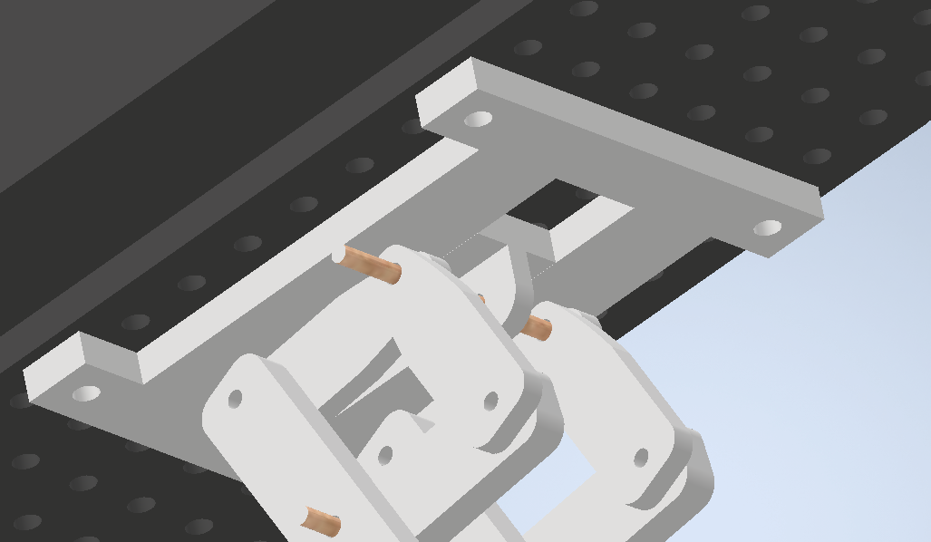
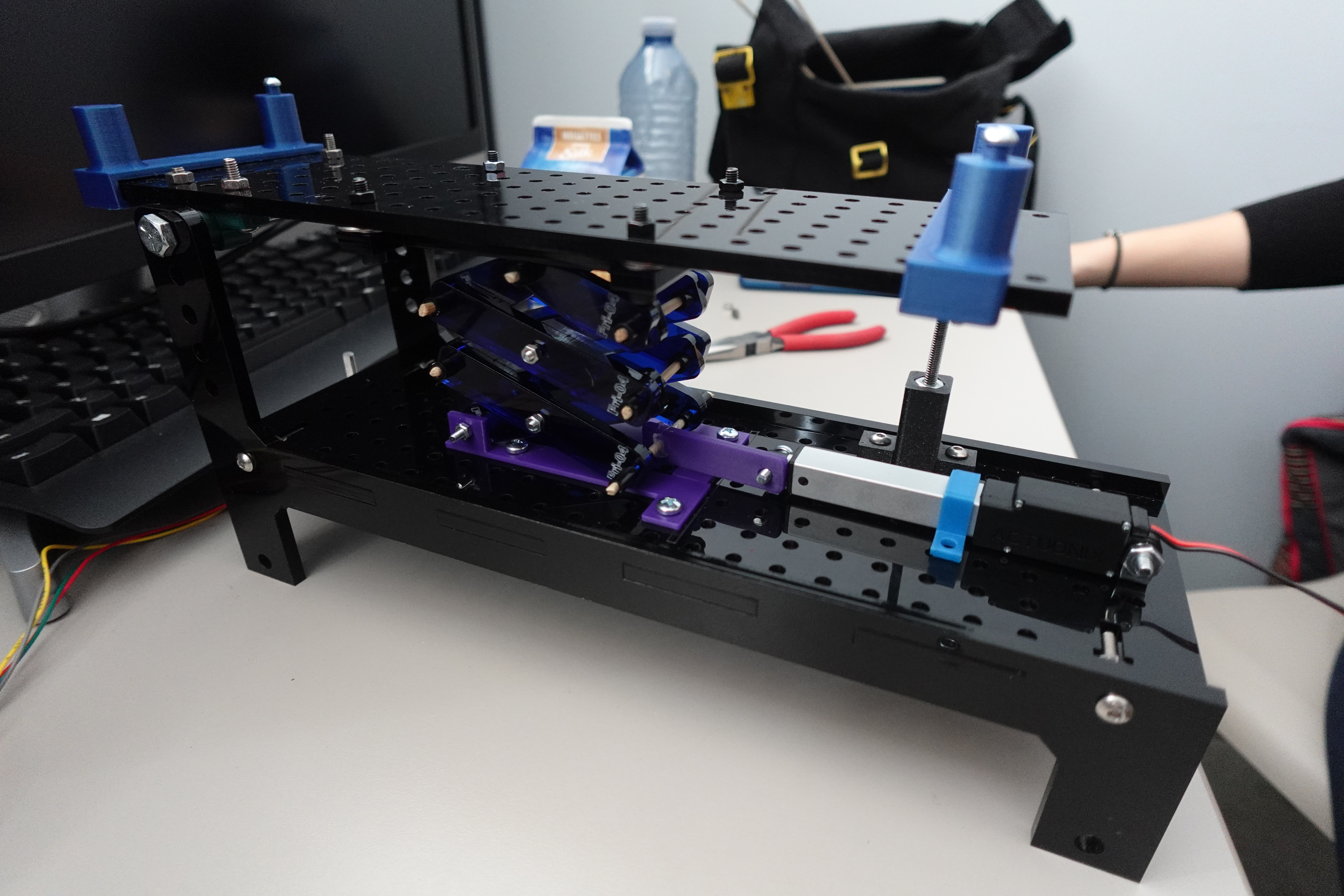
The “after trying it IRL” part refers to changes made somewhat last-minute– the team member with a 3D printer being here essential– where we added a plate by which the slider at the top of the mechanism “hooks in” to the groove it’s sliding along. A previous version, right up until fabrication and testing, worked with the slider that runs along the top of the hopper essentially being held in only by gravity. This worked OK in the CAD assembly:
It actually stayed in pretty well in reality as well, but required a larger amount of force to get “unstuck” from its resting position when the actuator started to move. The fix was fairly simple, and only required re-fabricating one part; we decided to raise the slider rail off of the top with a few washers, and add thin pieces sticking off the slider that would be trapped between the slider rail and the hopper, so all the force of the actuator could only be translated in one direction.
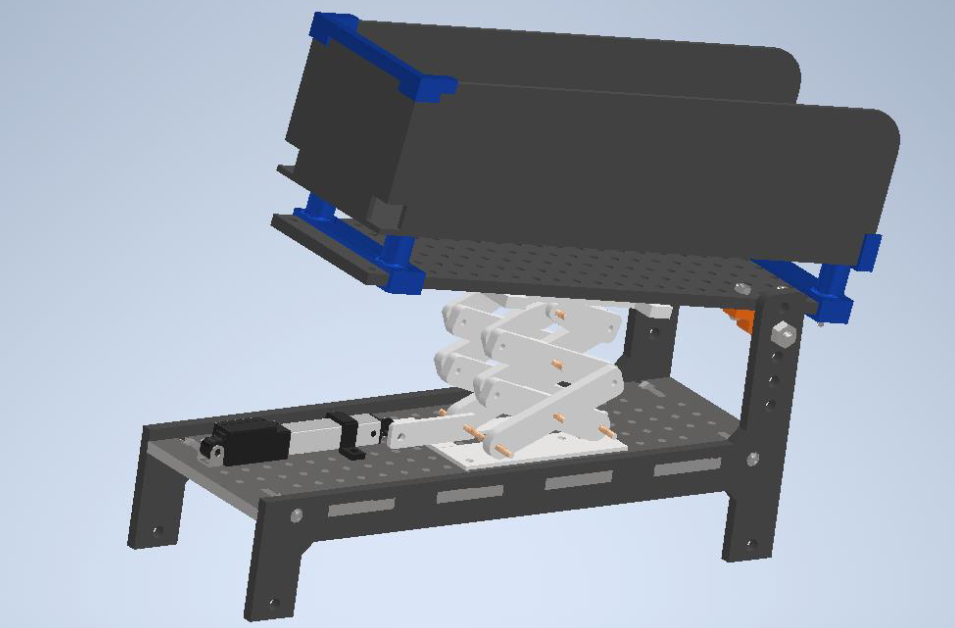
Though there was no reason to think this would work any worse than the previous version, it was a little nerve-wracking in that we didn’t have the opportunity to actually test it on the real-life hopper until our final presentation. However, it fit in perfectly:

And when attached to the moving robot that it had been the computing team’s job to code, successfully put the recycling in the bin, at least the time that we were being marked on it:
As well as lucking out with excellent groupmates on this project, this was a fun experience because it involved a challenge that we wouldn’t necessarily have thought to set ourselves, with obvious standards of success or failure, and we had the fabrication resources to execute our design successfully. In making the CAD model (and re-making it… and re-making it…) I definitely learned some lessons that will (hopefully) make the next time I make something of this nature easier. For instance, an in-retrospect-obvious bit of planning that did not occur to me when I first started the model: why not just decide what size of screws you’re going to use based on what’s easily available at the hardware store, and then make your parts with holes of that size? Instead of doing that, by the end of the project I’d accrued a kind of CAD-cruft whereby the design included three different sides of holes: 4mm for the parts that needed to connect directly to the hopper, 3mm holes requiring screws that I drove all over town looking for, and holes for the dowels that started out 3mm and then had to be changed to match the size of dowel we ended up using.
Also, I learned to absolutely do not under any circumstances make changes to your parts inside your assembly file, even though that is a thing that Autodesk Inventor absolutely allows you to do, because then when you want to actually fabricate the parts, which requires exporting to a 3D-printable format from the individual parts files, you will have a bunch of parts that do not actually have the changes you want to have made to them, and when you ask a TA for help with that situation and explain how you got there, she will only shake her head sadly and say “Oh… dawg…”
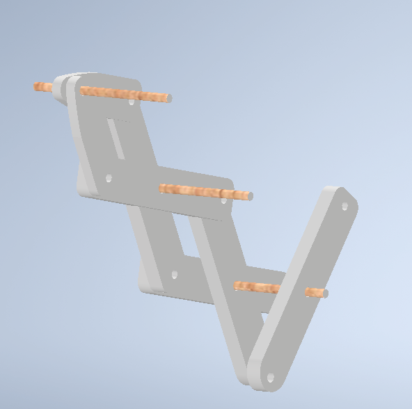
We ended up dismantling the mechanism, because that thing had $40 worth of screws on it that I wanted back to be able to re-use, and the teammate who did most of the fabrication wanted to keep the other bits. However, we did each keep a single linkage, which now sits on my bookshelf as a souvenir:

Computing
The second project introduced the use of a virtual invironment built by Quanser. The project involved programming a robotic arm to pick up and put down boxes in various locations; since the actual robotic arms are expensive and delicate, the virtual environment allowed you to make mistakes without fear of damaging the equipment. Here was my final code for the task, which was to randomly spawn six boxes of different colours and sizes and then drop them off at a location that depended on the colour and size.
  `ip_address = 'localhost' # Enter your IP Address here
project_identifier = 'P2B' # Enter the project identifier i.e. P2A or P2B
#--------------------------------------------------------------------------------
import sys
sys.path.append('../')
from Common.simulation_project_library import *

hardware = False
QLabs = configure_environment(project_identifier, ip_address, hardware).QLabs
arm = qarm(project_identifier,ip_address,QLabs,hardware)
potentiometer = potentiometer_interface()
#--------------------------------------------------------------------------------
# STUDENT CODE BEGINS
#---------------------------------------------------------------------------------

def pick_up_container(size):
    if size == 'small': #if container is small, close the gripper a larger angle
        angle = 35 #IF YOU CHANGE THESE ANGLES, ALSO CHANGE THEM IN DROP OFF FUNCTION
    else: #if container is large, close the gripper a smaller angle
        angle = 30
    arm.move_arm(0.6, 0.003, 0.02) #trial pickup location-- could use improvement
    time.sleep(2)
    arm.control_gripper(angle)
    time.sleep(2)
    arm.move_arm(0.406, 0.0, 0.483) #this is the home position
    time.sleep(5)

def rotate_qarm_base(colour):
    positionsuccess = False
    old_reading = 0.5
    while not positionsuccess:
        new_reading = potentiometer.right()
        delta = new_reading - old_reading
        increment = 348*delta
        arm.rotate_base(increment)
        time.sleep(0.2)
        print(potentiometer.left(),potentiometer.right())
        old_reading = new_reading
        positionsuccess = arm.check_autoclave(colour)
        if positionsuccess:
            final_reading = arm.effector_position()
            print("Arm is in position")
            return final_reading
        else:
            print("Arm is not in position")


def drop_off_and_return(colour, size, final_reading):
    arm.move_arm(final_reading[0], final_reading[1], final_reading[2])
    arm.activate_autoclaves()
    if size == "large":
        arm.open_autoclave(colour)
    else:
        pass
    print("Please move left potentiometer: between 0.5 and 1 for small, all the way to 1 for large.")
    potentiometerused = False
    while not potentiometerused:
        if 0.5 < potentiometer.left() < 1 and size == "small":
            potentiometerused = True
            arm.rotate_elbow(-15)
            arm.rotate_shoulder(35)
            time.sleep(1)
            arm.control_gripper(-35)
            time.sleep(2)
            arm.home()
        elif potentiometer.left() == 1 and size == "large":
            potentiometerused = True
            arm.rotate_elbow(15)
            arm.rotate_shoulder(30)
            time.sleep(0.5)
            arm.control_gripper(-30)
            time.sleep(2)
            arm.home()
            arm.open_autoclave(colour, False)
        else:
            pass

def get_container_info(container):
    if container  == 3 or container == 6:
        colour = 'blue'
    elif container == 1 or container == 4:
        colour = 'red'
    else:
        colour = 'green'
    if 1 <= container <= 3: #Containers 1, 2 and 3 are small containers
        size = "small"
    else: #containers 4, 5 and 6 are large containers
        size = "large"
    return [colour, size]


def main():
    import random
    usedcontainers = [] #starts at length 0, will be populated with used containers
    while len(usedcontainers) < 6:
        container = random.randint(1,6) #gets a container with a value in the given range
        if container in usedcontainers:
            pass #We want to use each container only once
        elif container not in usedcontainers:
            arm.spawn_cage(container)
            usedcontainers.append(container)
            containerinfo = get_container_info(container)
            colour = containerinfo[0]
            size = containerinfo[1]
            pick_up_container(size) #picks up the container
            final_reading = rotate_qarm_base(colour)
            time.sleep(0.5)
            drop_off_and_return(colour, size, final_reading)
            time.sleep(0.5)
            time.sleep(0.5)
        else:
            print("Random value error!")


if __name__ == "__main__":
    main()

#---------------------------------------------------------------------------------
# STUDENT CODE ENDS
#---------------------------------------------------------------------------------`
Modelling
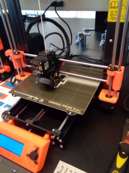
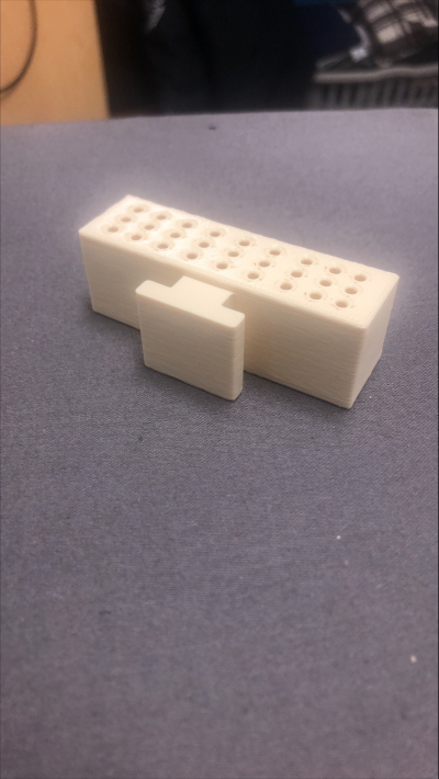
Although I was tasked with writing the code for the concept, there was also a modelling and 3D printing aspect to the project, the idea being to create a box that the robotic arm could pick up and put down. Unfortunately, because of constraints on the availability of 3D printers, print time had to be kept under 2 hours. Since most large 3D print jobs take much longer than that, the box had to be scaled down until it was, shall we say, very cute. However, getting to use the 3D printers did provide an interesting view of how they work. The first print job failed, with the first few layers of the box looking like this:
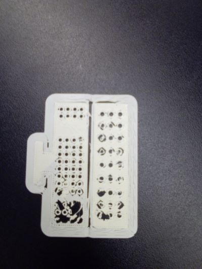
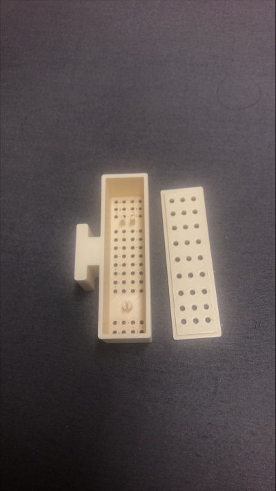
After a quick consultation with my spouse, who works at the Makerspace at the public library and helps with the 3D printers (and embroidery machine, and laser cutter, etc– did you know the public library could do all that?), it seemed that there wasn’t a fundamental problem with the design (I had thought at first that there were too many holes in the box, and the filament wasn’t able to trace them accurately.) Instead it was just an adhesion problem, and could be fixed by either trying it again or, to be sure, using a glue stick on the printer plate. The next try was successful:
In this project, we were tasked with creating– or rather lightly editing, since much of the design was done for us– a design for a wind turbine blade based on one of four scenarios.
The scenario my group was assigned reads as follows:
You are a part of a group of volunteer engineers in Engineers Without Borders (EWB) that is designing a simple wind turbine for the Guatemalan city of Quetzaltenango. This Guatemalan village is currently off the grid [sic]* and EWB aims to build a wind turbine that can provide enough energy to power simple electrical devices like LED lights. Villagers will assemble multiple units of these simple turbines, which should be long lasting and require little maintenance. Your task is to design a simple wind turbine that is suitable for easy assembly by the villagers with widely available materials. Source: Wired, ‘Engineers Without Borders Bring Tech to Villages Without Power’, 2008. [Online]. Available: https://www.wired.com/2008/03/engineers-without-borders-bring-tech-to-villages-without-power. [Accessed: 24 – July - 2020].
Since the scenario was based on a real-world project, naturally I was curious to find out what happened with it. The Wired article says that “The turbine was created by the Appropriate Technology Design Team of EWB’s San Francisco chapter. Team members like Malcolm Knapp and Heather Fleming spend their nights and weekends inside D2M’s design shop trying to perfect low-tech gadgets for people 2,500 miles away.”
There are also links in the article: one to the Appropriate Technology Design team, a victim to link rot, and one to the San Francisco chapter of EWB’s website. An inspection of that site revealed that the ATDT changed its name to “R&D Group” in 2014. Unfortunately, the link to the “new” R&D group’s website is also dead, and the Guatemala wind turbine project is not listed on that page’s summary of previous ATDT/R&D group projects.
Which is somewhat anticlimactic, in terms of being able to figure out what– if anything– actually happened with the project. However, from the moment I read the original article, I was put in mind of a passage from Tracy Kidder’s Mountains Beyond Mountains, a book that made an enormous impression on me when I first read it, and of which I was reminded by the death of Paul Farmer in February of 2022. In the book, describing Farmer’s early contact with the collaborators and patients who would define his career and the transformative impact of Latin American liberation theology on his work, Kidder writes:
Farmer was learning about the great importance of water to public health, and he was conceiving a great fondness for technology in general, and also scorn for “the Luddite trap.” He liked to illustrate the meaning of that phrase with the story of the time when he came back to Cange from Harvard and found that Père Lafontant had overseen the construction of thirty fine-looking concrete latrines, scattered through the village. “But,” Farmer asked, “are they appropriate technology?” He’d picked up the term in a class at the Harvard School of Public Health. As a rule, it meant that one should use only the simplest technologies required to do a job.
“Do you know what appropriate technology means? It means good things for rich people and shit for the poor,” the priest growled, and refused to speak to Farmer again for a couple of days.
Lafontant was also supervising the construction of a clinic in Cange—the South Carolinians had put up the money. The facility would have a laboratory, of course. Farmer got hold of a pamphlet about how to equip labs in third world places published by the World Health Organization. It made modest recommendations. You could make do with only one sink. If it wasn’t easy to arrange for electricity, you could rely on solar power. A homemade solar-powered microscope would serve for most purposes. He threw the booklet away. The first microscope in Cange was a real one, which he stole from Harvard Medical School. “Redistributive justice,” he’d later say. “We were just helping them not go to hell.”
All throughout this project, the words of Père Lafontant, a Haitian Episcopal priest who died of COVID-19 in 2021, were on my mind. When we were choosing objectives, the student groups who had scenarios taking place in rich countries chose objectives that prioritized “good things for rich people”: a wind farm capable of powering an entire city or country, a roof generator to help people reduce their power bills. Which begs the question: we we, in our design prioritizing low cost and portability, falling into Farmer’s Luddite Trap? And were the original EWB Appropriate Technology Design Team, named after the very concept that Lafontant so colourfully characterized as “shit for the poor,” doing the exact same thing? What kinds of assumptions do we make about the end users of our devices, when we design them to be technology that wouldn’t be sufficient for our own needs? And what would a preferential option for the poor look like in technology design?
*Quetzaltenango is not an off-the-grid village, it is a major city with a distinguished Mayan history. In the article, it is clear that the original intention was for the city to be a manufacturing centre for turbines that would then be transported to outlying villages.