Project 3
Project 3 was, in my opinion, the most interesting and useful of the four projects of the 1P13 course, as it consisted of a well-defined problem with clear metrics for evaluating how successful your design was. As in the previous project, the groups of students were divided into “Modelling” and “Computation” sub-teams, which had largely seperate goals, though the overall storyline justifying the assignment had to do with the two sub-teams combining their designs into a single system for sorting recycling.
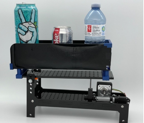
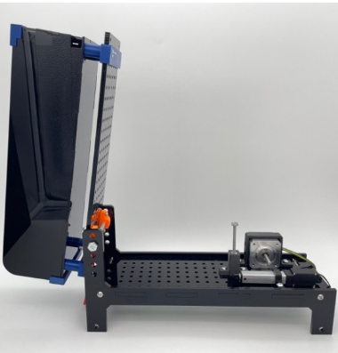
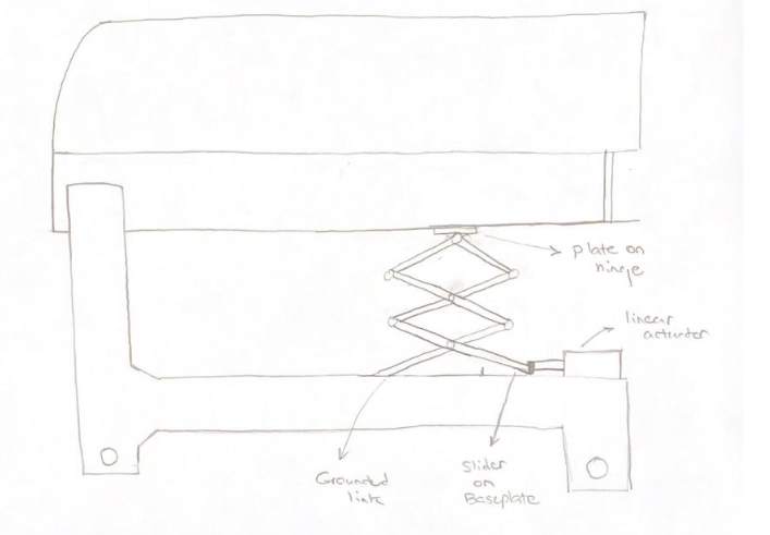
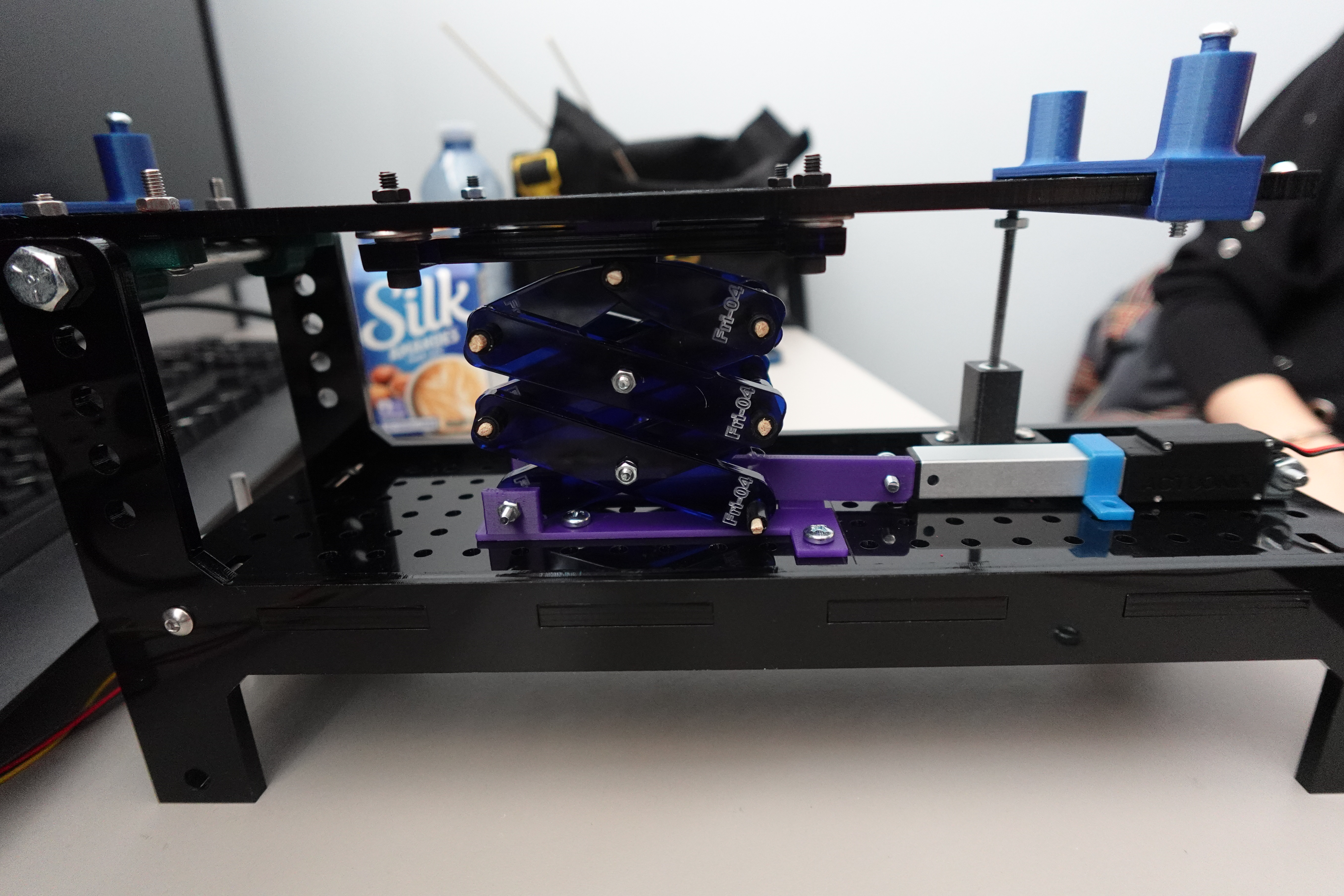
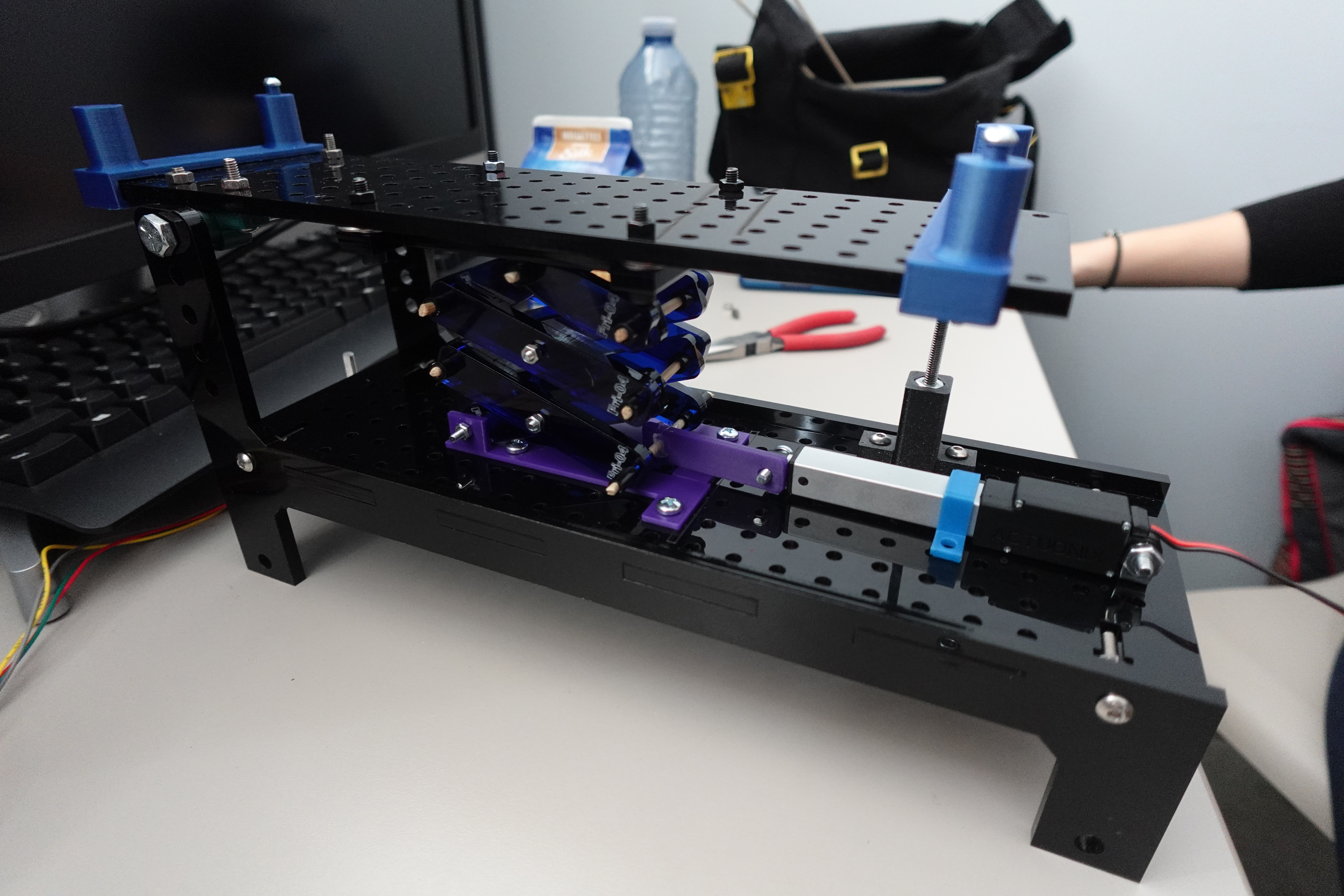
Having done the computing sub-team for project 2, I was on the modelling sub-team for this project. The goal of the physical construction for this project was to design a mechanism that would use either a rotary or linear actuator to raise and lower the container on the upper part of a pre-fabricated hopper, so as to dump out recycled containers contained therein, as in these photos of the starting point provided in the assignment document:
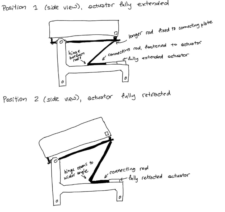
Initially, each member of the group was tasked with coming up with different concepts of how this could be accomplished. My concept for how the linear actuator could be used was pretty much the simplest possible design… a stick. It’s a stick. It raises the top when the linear actuator retracts. Needless to say, I wasn’t exactly jazzed up about the challenges of making this one:

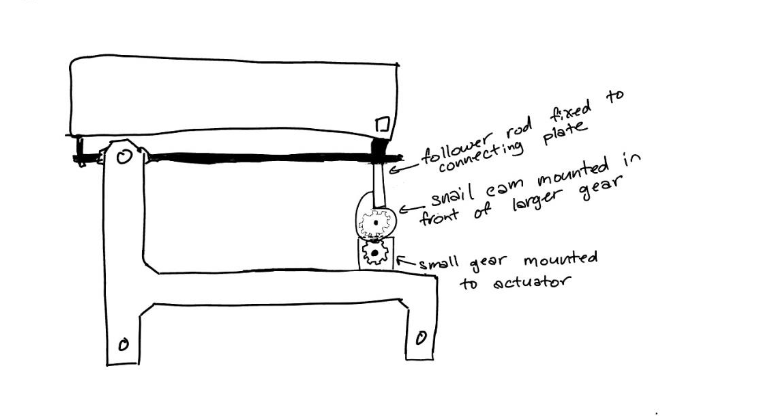
My design for how the rotary actuator could be used was, in my own humble opinion, cooler: it used a set of gears and a cam-and-follower setup to raise and lower the upper platform cyclically as the actuator rotated.
Unfortunately, once we compared this design to the actual size of the hopper our mechanism would need to fit onto, it was clear that the length of cam required to raise the upper platform to a sufficient angle to dump the recycling would not actually fit in the space we had available for the mechanism. actually, all three of us on the modelling team had generated one idea that was cool but impractical, and one that was less visually exciting but more likely to work, all of which were variations on the “it’s a stick, it makes the linear actuator push up” concept.
In the end, we settled on the most highly-developed version of the “it’s a stick” concept on the market, a scissor lift.
Next we needed to CAD it. Unless the thing is large enough that it makes sense to have different people working on different parts of it, which this wasn’t, it’s a little bit impractical to have multiple people “make” a CAD model of the same object at the same time; instead, the two of us who wanted to work on the CAD model both made our own versions, and we’d use whichever one ended up working better; and the member who preferred to work on fabrication, and had access to a private 3D printer, worked on that side. Unfortunately, the two of us who wanted to make a CAD model were both so enthusiastic about jumping into it that we failed to notice there were downloadable CAD files representing the already-fabricated parts of the hopper that you could use to make sure your mechanism would actually fit, and we showed up at the next class with two separate models of the mechanism, neither of which actually fit the parts provided. Oops! We fixed that for the next class and both attached our models to the given files. In an unexpected sudden death round of “who’s CAD model works better,” something went oddly and catastrophically wrong with the contraints on my classmate’s model, which had been working just fine, right before we were about to show it to a TA, so mine it was, kicking off a long iteration of files on my computer named things like “preminary CAD”, “final CAD”, “really final CAD”, “Actually final CAD after trying it IRL”, etc, as well as a large array of stray files featuring parts in amusingly unphyiscal situations:

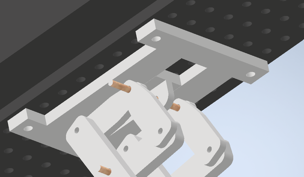
(The one aspect of Project 4 that was unambiguously better than Project 3, for me personally: simply giving files version names… genius.) Anyway, “Actually final CAD after trying it IRL” looked like this:


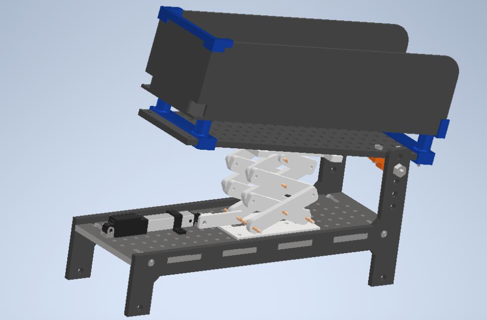
The “after trying it IRL” part refers to changes made somewhat last-minute– the team member with a 3D printer being here essential– where we added a plate by which the slider at the top of the mechanism “hooks in” to the groove it’s sliding along. A previous version, right up until fabrication and testing, worked with the slider that runs along the top of the hopper essentially being held in only by gravity. This worked OK in the CAD assembly:
It actually stayed in pretty well in reality as well, but required a larger amount of force to get “unstuck” from its resting position when the actuator started to move. The fix was fairly simple, and only required re-fabricating one part; we decided to raise the slider rail off of the top with a few washers, and add thin pieces sticking off the slider that would be trapped between the slider rail and the hopper, so all the force of the actuator could only be translated in one direction.
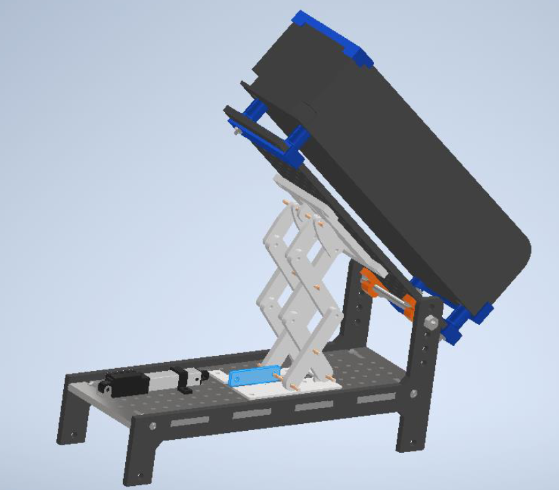
Though there was no reason to think this would work any worse than the previous version, it was a little nerve-wracking in that we didn’t have the opportunity to actually test it on the real-life hopper until our final presentation. However, it fit in perfectly:

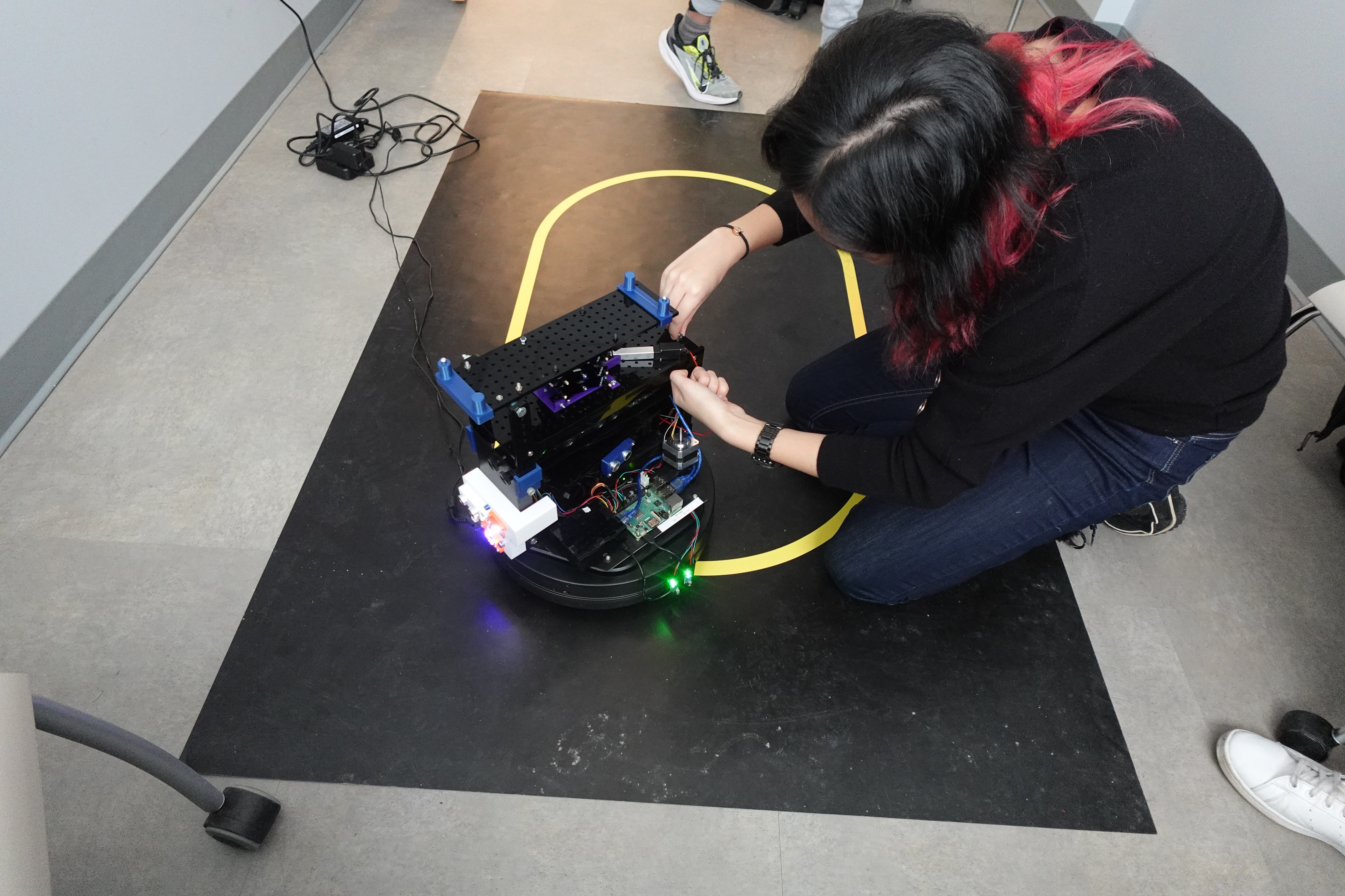
And when attached to the moving robot that it had been the computing team’s job to code, successfully put the recycling in the bin, at least the time that we were being marked on it:
As well as lucking out with excellent groupmates on this project, this was a fun experience because it involved a challenge that we wouldn’t necessarily have thought to set ourselves, with obvious standards of success or failure, and we had the fabrication resources to execute our design successfully. In making the CAD model (and re-making it… and re-making it…) I definitely learned some lessons that will (hopefully) make the next time I make something of this nature easier. For instance, an in-retrospect-obvious bit of planning that did not occur to me when I first started the model: why not just decide what size of screws you’re going to use based on what’s easily available at the hardware store, and then make your parts with holes of that size? Instead of doing that, by the end of the project I’d accrued a kind of CAD-cruft whereby the design included three different sides of holes: 4mm for the parts that needed to connect directly to the hopper, 3mm holes requiring screws that I drove all over town looking for, and holes for the dowels that started out 3mm and then had to be changed to match the size of dowel we ended up using.
Also, I learned to absolutely do not under any circumstances make changes to your parts inside your assembly file, even though that is a thing that Autodesk Inventor absolutely allows you to do, because then when you want to actually fabricate the parts, which requires exporting to a 3D-printable format from the individual parts files, you will have a bunch of parts that do not actually have the changes you want to have made to them, and when you ask a TA for help with that situation and explain how you got there, she will only shake her head sadly and say “Oh… dawg…”
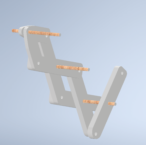
We ended up dismantling the mechanism, because that thing had $40 worth of screws on it that I wanted back to be able to re-use, and the teammate who did most of the fabrication wanted to keep the other bits. However, we did each keep a single linkage, which now sits on my bookshelf as a souvenir: